
The main tracks cut across the railway park; thus, separating the viewing platform from the rest of the park. One option is an overhead bridge across the tracks. Or you can go underneath.

I chose to go underneath.
Challenges with Going Underneath
Going underneath presents a few challenges for me as you can see from this contour drawing.
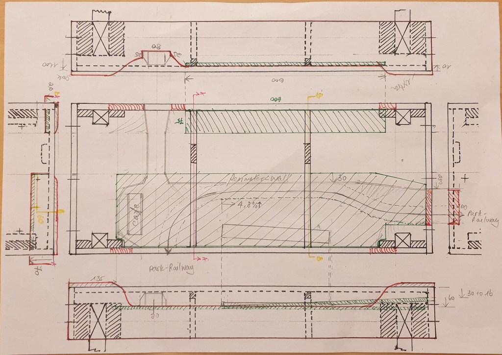
- The positions of the module legs and support guides on the left side take up 132mm per leg; thus, the tunnel needs to be further away than originally planned.
- Each module is 140mm deep (minus the baseboard for the main tracks. The positions of the module connectors need to be considered.
- I wanted the operator side to be 60mm lower than top of the module (1100mm above the flat floor) and a 4.8% gradient to the next module.
- The main electrical wires run underneath the main track baseboard.
- Sufficient working space underneath the modules when operating in case I need to.
Prototyping the Pedestrian Tunnel Design
Parkett floor laminations 3mm allowed me to test my design. This one is 280mm long and 80mm wide. I hanged the prototype on the side of the end module template and marked any changes I wanted.


My club member Rene gave me two H0 figures to test the height of the tunnel. Although it is a pedestrian tunnel, park service vehicles (e.g. Preiser 33260 Ford Transit) (1:1 scale 2.4-27m high; 2.5m wide) could pass through.
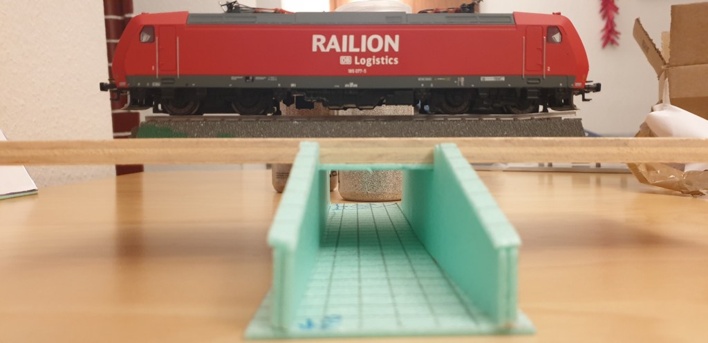
As the tunnel will be hanging from the baseboard, the load and stability test was not necessary. I will put a 5mm board below the tunnel for better support and for bridging one side of the module fascia to another.

One thought on “Prototyping a Pedestrian Tunnel for Park Connection”